Do you have trouble keeping your plants alive? Have you ever wanted to build an automatic plant irrigation system? Want to build something cool with your Raspberry Pi? With some sensors, actuators and the PiShield, you can make your very own network controlled, automated irrigation system. For this project, you will need:
- Raspberry Pi board with PiShield, Power supply and SD card with Raspbian. (PiShield kits are available here if you don’t have a Raspberry Pi already)
- I-CubeX Moist Sensor
- I-CubeX Switch Actuator
- Valve Actuator and a 10 to 12V DC power supply
- 4mm irrigation tubing
- Water Tank (4 litre milk jug, etc)
Hardware Setup and Overview
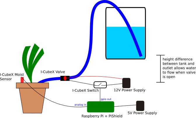
The basic premise of the system is as follows:
- The watering is done via a siphon. A tube connects to the water tank source at a higher point compared to the outlet at the plant. As long as the tube is filled with water, when the outlet is opened, water flowing out at the bottom will draw reduce the pressure in the upper parts of the tube, which sucks water from the tank. This system does not require the use of pumps, which may be damaged if it runs when the tank is empty. The drawback is that to get the system started, you’ll have to prime it by filling up the tube with water. This can be done by sucking the tube at the outlet. If you want to use a pump instead, you can simply replace the valve used in this example with your pump and appropriate power supply.
- The Moist sensor is embedded into the soil and provides a variable voltage output as the moisture level changes. This value is read by the Raspberry Pi via the PiShield
- When the moisture level decreases beyond a certain threshold, the Raspberry Pi emits an output to trigger the watering
- The water valve actuator requires 12V to turn on. This is done by the Switch actuator, which allows a low output signal from the RPi’s GPIO pin to switch the 12V supply to activate the valve.
Electrical Wiring
The Moist sensor simply plugs into the analog input port of the PiShield.
The trickiest part of this project is hooking up the external 12V power supply for the water valve and the Switch actuator to the GPIO header. Following shows the the connections:

Below is a photo of our setup. You may choose longer wires to fit your situation.

Here we see the 12V leads (back and red wires) connected to the Valve, as well as the Switch. In this particular case, since the Valve does not have polarity, it is possible to switch the + and – power supply wires. However, it is good habit to know which is which since many devices require the correct polarity to operate!
If the Switch actuator doesn’t turn on and off normally, but delays its switching action and/or oscillates for a few seconds, you need to add a so-called “Flyback” diode (eg. a 1N4149) across the terminals of the Switch actuator to eliminate the voltage spikes caused by the Valve when it is turned on or off. Connect the diode’s cathode (usually indicated on the diode as a black line) to the terminal that’s connected to 12V.
The following photo shows a close-up of the screw terminal connections that secure the wires to the I-CubeX Switch.

In the next photo we see the modified plug of the Switch terminal so that it can be used with the PiShield GPIO output header. The Switch also requires a 5V supply, so we break out the that pin as well and extend it:

As the first version of the PiShield was primarily designed for sensors, to use actuators requires this modification. We will be looking at ways of making it easier to attach actuators in the future.
Once everything is hooked up, you can test it by connecting the 12V power and booting up the Pi. From there, one of the simplest ways to trigger the Valve is using the following wiringPi terminal commands:
gpio mode 2 out #(sets pin to output mode)
and then:
gpio write 2 1 #(to turn on the Valve)
gpio write 2 0 #(to turn it off).
You should hear the solenoid in the valve click as you turn it on and off.
Here pin 2 refers to the wiringPi numbering scheme, which is the first of the two GPIO headers are on the PiShield.
Connecting to the water tank
The follow photo shows how everything is hooked up:

Software Configuration.
To build the control application, we use the node-red platform. A more detailed description of how the flow works is presented here. The full code can be copied from here and pasted into node-red. The node-red flow editor is accessible at raspberrypillocal:1880/ (assuming node-red is running), and the dashboard at raspberrypi.local:1880/ui once the flow is deployed.
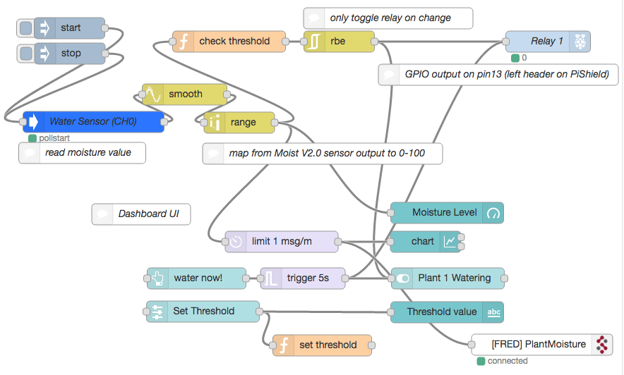
Of course, this example is only the beginning. Using the power of node-red, you can easily extend this system by providing more interesting interfaces such as a chart for plotting the history of moisture levels, or send events via connected platforms to provide notifications to receive remote updates, etc… We look forward to hearing what interesting things you may come up with!
Pingback: node-red flow for automated plant watering system – Infusion Systems
Pingback: Adding a Physical Gauge to a Humidity Meter – Infusion Systems